Surface Lattice Resonance (SLR) Generators (CODE SLR-01)
SPECIFICATIONS
| Substrate | Glass |
| Substrate Diameter | 25,4 mm |
| Coating Material | Gold |
| Coating Thickness | 50 nm |
| Active area^ | 5x5 mm2 |
| Period between structures^ | 700 nm |
| Diameter of structures | ~400 nm |
| Height of structures | ~100 nm |
| SLR for p-polarization at 80 of AOI+ | |
| Wavelength | ~836 nm |
| FWHM* | < 30 nm |
| Depth** | ~45% |
|
Q-factor*** | ~30 |
| SLR for s-polarization at 80 of AOI | |
| Wavelength | ~708 nm |
| FWHM | < 25 nm |
| Depth | ~35% |
| Q-factor | ~30 |
| Price | on request |
^ available custom size or period
+AOI - Angle of light incidence
REFLECTANCE SPECTRA
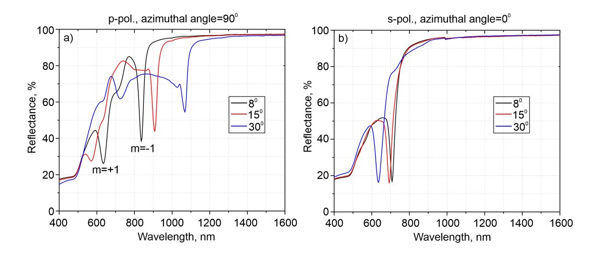 Figure 1. a) Reflectance spectra of microbumps array with period
700 nm in 50 nm thick gold film for p-polarized (a) and s-polarized (b).
Spectra were measured for the different angles of light incidence: 8° (black
curves); 15° (red curves); 30° (blue curves).
Figure 1. a) Reflectance spectra of microbumps array with period
700 nm in 50 nm thick gold film for p-polarized (a) and s-polarized (b).
Spectra were measured for the different angles of light incidence: 8° (black
curves); 15° (red curves); 30° (blue curves).
DESCRIPTION
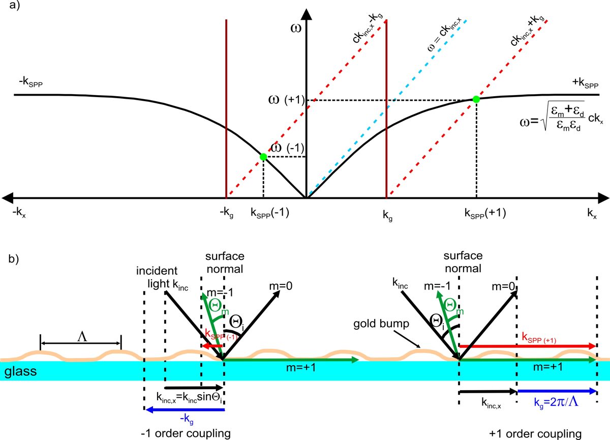
Figure 2. a) Dispersion relations of light and surface
plasmons polariton. The x-component
of the incident light (kinc,x) is shown by the dashed cyan
line. The diffraction of the incident light by the grating results in the lines
ckinc,x + kg
and ckinc,x − kg (the
dashed red lines). The intersection of the diffracted light lines with the
plasmon dispersion lines kSPP
and − kSPP indicate the
frequencies of the excited plasmons polaritons (green dots). b) The relationship between the tangential component of the incident
light wavevector kinc,x (black), grating vector kg (blue), and the wavevector
of surface plasmons polaritons kSPP
(red). kSPP(-1) and kSPP(+1) are wavevectors of
the surface plasmons polaritons coupled
with -1 and +1 diffraction orders, respectively. Θi is
the angle of incident light; Θm is the angle of diffracted light; m is the
diffraction order; Λ is the period of the gold bumps array.
The
grating coupling of surface lattice plasmons is schematically explained in Figure 2.
The surface lattice plasmons excitation condition is satisfied when the incident light
dispersion curve (the black lines in Figure 2a) crosses the lines ckinc,x + kg
and ckinc,x − kg
(the dashed red lines in Figure 2a). The intersection of the diffracted light
lines with the plasmon dispersion lines kSPP
and − kSPP indicate the
frequencies of the excited plasmons (green dots in Figure 2a). The graph shows
that the surface plasmons excitation can occur at two different frequencies ω(+1) and ω(-1) when the angle of
incidence is between 0° and 90°. If the incident light impinges normally to the
surface, then the plasmons are excited at a single frequency. The positive and negative vectoral
solutions correspond to the rightwards and leftwards propagating surface plasmons
having different frequencies (Figure 2b).
The resonant wavelength of surface lattice plasmons for p-polarized light can be expressed:
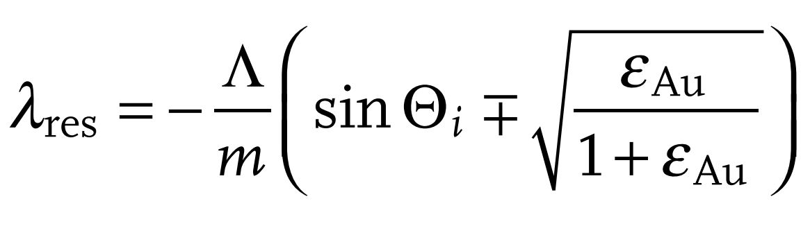
The resonant wavelength of surface lattice plasmons for s-polarized light can be expressed:
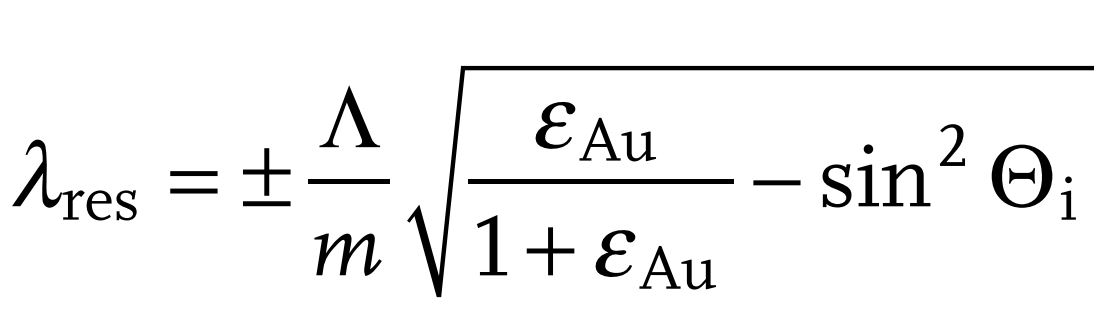
where Λ is the period of the grating; m is diffraction order; Θi is the incident angle of light; εAu is the dielectric constant of gold.
The theoretically resonant wavelengths λres depending on the incident angle Θi for p-polarization are represented by red and black solid lines in Figure 3a. The experimentally measured surface lattice plasmon resonances of produced elements are represented by data points in Figure 3a, which perfectly fit these curves (red circles for m=- 1 and black squares for m=1). When the incident light is s-polarized and the sample is rotated along the grating lines, only a single resonance peak is observed. The resonance peak shifts toward shorter wavelengths by increasing the incident angle Θi. The measured resonance peaks of elements (triangles in Figure 3b) are in good agreement with the theoretical calculations.
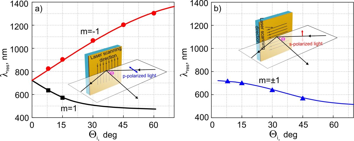
Figure 3. The theoretically calculated dependence of resonant wavelength of surface lattice plasmons on the incident angle of light (solid lines) and the experimentally measured data points (squares, circles, and triangles) of plasmonic resonances using a spectrophotometer, when the incident light is p-polarized and φ=90° (a), and when the light is s-polarized and φ=0° (b). The grating period is Λ=700 nm.
PHOTOGRAPHS AND SEM MICROGRAPHS
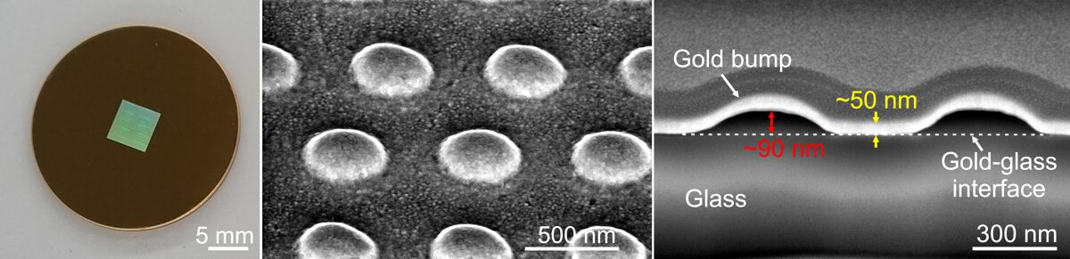
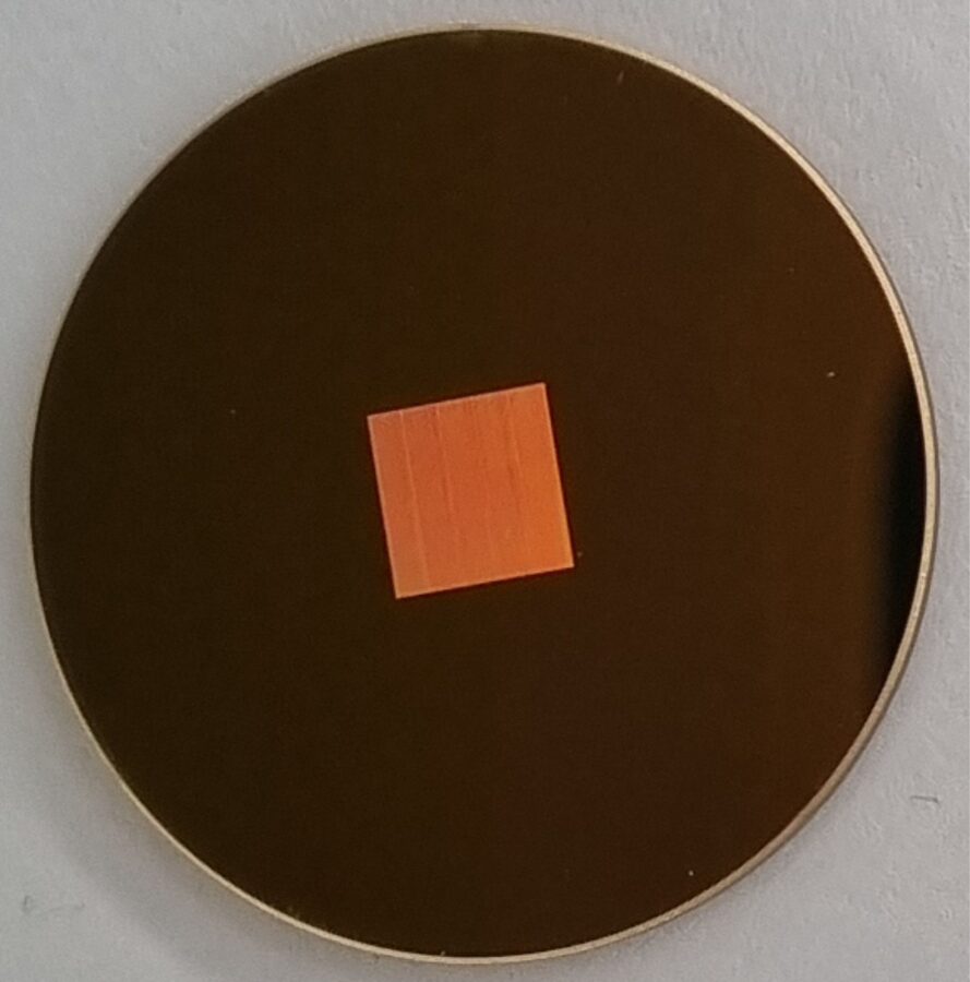
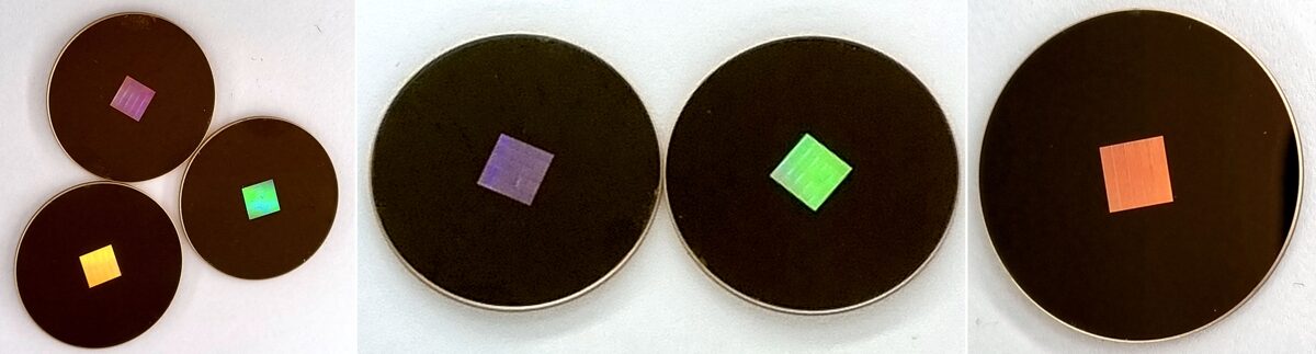 Figure 5. Photographs of SLR-01 element.
Surface Lattice Resonance (SLR) vs Localized surface plasmon resonance (LSPR)
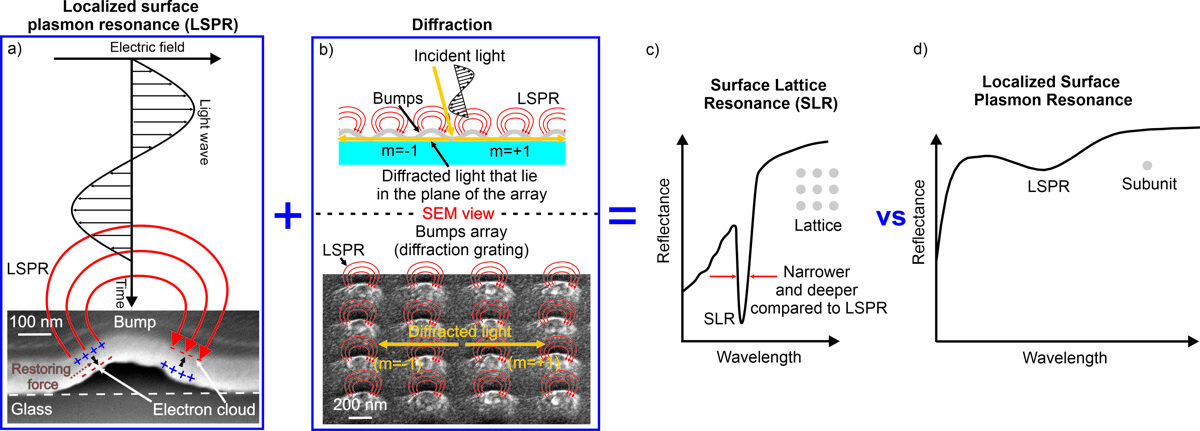
An orderly arranged microbumps array acts as a diffraction grating, therefore exists the conditions when the diffracted light of a certain wavelength and incident angle lies in the plane of the array (Figure 6b). This wavelength for a given grating is called “Rayleigh’s wavelength” (λRA). The considered diffracted light is evanescent and propagates along the surface of the array. The interaction of diffracted light with the LSPR mode of microbumps in a plasmonic array results in SLR (surface lattice resonance) mode (Figure 6c). The interaction efficiency depends on the tuning of the LSPR and Rayleigh’s wavelengths. Theoretical studies have demonstrated that near-field coupling is much more efficient when the LSPR wavelength of the isolated subunit (λLSPR) is close in value to the Rayleigh wavelength (λLSPR ~ λRA). The obtained surface lattice resonance is narrower and deeper compared to the localized surface plasmon resonance (Figure 6d).
APPLICATIONS
- Optical sensing
- Surface-enhanced Raman Spectroscopy (SERS)
- Plasmonic lasing
- Light absorption
- etc.
The proposed product can be exploited as a plasmonic sensor without the use of tracers for the detection of analytes (an advantage over fluorescent sensors) or for real-time monitoring of various chemical reactions.